
THE AR-2c+ DATALOGGER
GENERAL CHARACTERISTICS
|
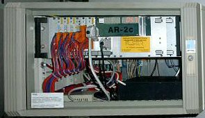
| fig.1. The AR-2c+ Datalogger |
The AR-2c+ Datalogger is a development of the AR-2c extending its capabilities by:
- logging more - up to 188 binary signals
- implementing 16-channels' binary inputs boards WC-16
- the possibility of using the communication cards for PLC controllers
- connecting one or more additional - remote displays for displaying machine's velocity or other information in remote places
- operation in the LAN by means of implementing a hardware RS485 - ETH converter or by a proxy server software
- the capability of performing local printouts of chosen signals' charts in "on-line" mode
The 16 binary inputs' boards WC-16
|
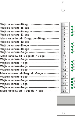
| fig.2. The 16 binary inputs' boards WC-16 |
The 16 binary inputs' board is prepared to reading input signals at input voltages range from 24 V DC to 48 V DC (or 48V - 110V). The module is constructed as a set of four blocks consisting of 4 channels each with a common ground line for each four. Input signals are connected to a 20 - pin WAGO connector. The connector's pin assignment description is shown on fig.2.
Each input channel is equipped with current limiter up to 5mA and voltage limiter serving for eliminating overvoltages' influence over the module's work and persistence. Input voltage less than 5V is treated as logical ''0''. In case of operation with input voltages in range of 48 - 110V an additional voltage drop is forced by an input resistor. Each input is assigned a signaling LED located on board's front panel above corresponding input pin.
Communication cards for PLC controllers
|
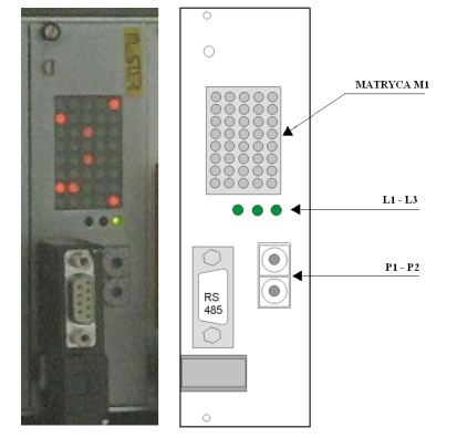
| fig.3. The PROFIBUS DP communication card's front panel |
For ensuring cooperation with hoist's control and shaft signaling systems based on PLC controllers' systems special communication cards for the AR-2c+ datalogger were developed. These communication cards provide an universal and easy to use different fieldbus interface for integration on the internal datalogger's bus. Depending on the communication card type one can integrate different fieldbus protocols e.g. PROFIBUS-DP, MODBUS RTU and other.
The AR-2c+ datalogger can be equipped with several communication cards (according to the demands) what can be one of following types:
- a dedicated PROFIBUS DP slave card (version I)
- a dedicated MODBUS RTU (master or slave) card
Irrespective of the type all communication cards consist of
- communication interface compatible with fieldbus type
- communication processor
- dual-port memory for accessing input signals and inter-bus communication
- signaling block (signaling LEDs), fieldbus connectors according to the standard, and rotary switches for station address setting (when needed, i.e. for slaves)
Communication cards, thanks to their universal construction, can serve for communication with different popular fieldbus interfaces:
- PROFIBUS DP
- MODBUS RTU
- specialized protocols
PROFIBUS DP (type I) specialized communication card
The front panel of the PROFIBUS DP (type I) communication card is shown on fig.3.
Apart from the fieldbus connector there are diode matrix M1 (8 x 5) consisting of 5 sets of 8 red LEDs indicating the state of chosen inputs and a set of 3 green LEDs: L1 - L3 serving for controlling of the transmission line state, and two rotary switches P1 and P2 where the station address on the PROFIBUS is set (don't change). On the first four rows (from the left side) of the M1 matrix two successive words of data sent by the PROFIBUS are displayed corresponding to the P2 switch on the front panel of CPU block (fig. 2.3) setting.
MODBUS RTU communication card
The card serves for integrating the MODBUS RTU protocol with AR-2c datalogger. On the front panel of the card two serial link connectors are available, one of them works in RS232, the second one in RS485 communication standard. The possible transmission speeds are 9600Bd, 19200Bd, 38400Bd and can be programmed in depending on the users' needs. The card can work as a MASTER or a SLAVE - the operation mode is to be chosen by a strapping on the card. In the MASTER mode the card can cooperate also with two PLC controllers.
Additional displays
|
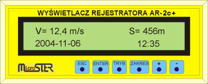
| fig.4. AR-2c+ Additional display |
The AR-2c+ datalogger can be additionally equipped with one or more remote display modules connected to the datalogger by a serial RS232 or RS485 (for greater distances) link. It can be placed on the operator's desk or other visible location. The maximum distance it can be located depends on the link type - for RS-232 it can be 25m, for RS-485 - 1200m and for modem link it depends on modem characteristic. One can connect multiple displays, according to the needs, the RS485 serial link enables simultaneous operation of several displays. The AR-2c+ display is shown on fig.4.
Networking capabilities
In order to improve the datalogger's performance the networking capability was introduced to the AR-2c+. The datalogger can be connected to the LAN in two ways:
- Hardware method - by using serial link/Ethernet (RS485 - ETH) converter
- Indirectly - via a proxy server application working on the computer sever station where the datalogger is connected by serial link to.
Every above method of connection to the network makes possible for the AR-2c+ datalogger to operate in the LAN as a common network data server.
"On-line" printing paging function
In order to widen the AR-2c+ datalogger functionality and to improve its servicing and maintenance paging to the ''on-line'' printing mode was introduced. All 188 binary and 8 analog signals in sets of 22 binary and 2 analog can be continuously output on the local OKI 280 printer. The printed page is chosen by means of two buttons located on the special inputs board's front panel or by the use of a special page choice switch module.
PARAMETERS
| PARAMETER DESCRIPTION | PARAMETER VALUE | |
| 1 | 2 | |
| Power supply | 18V - 30V DC or 100-260V AC | |
| Power supply tolerance | as above | |
| Power consumption | no more than 50VA | |
| Ambient temperature during work | 5 - 40oC | |
| Ambient temperature during transportation and storage | -40oC - +70oC | |
| Relative humidity at 30oC during work during transportation |
30...85% do 95% |
|
| Dimensions | 480 × 254 × 134 mm | |
| Weight | 7 kG | |
| Logging time after power down | no less than 1 hour** | |
| Binary inputs | quantity | 20 - 188 |
| input voltages | 24 V, 48 V, 220 V, 110 V DC | |
| input voltages tolerance | ±35% | |
| input currents | 4,5 - 10 mA | |
| scanning resolution (frequency) | 10 ms | |
| isolation | > 2500 V | |
| Analog inputs | quantity | up to 16 |
| input voltages | -10... +10 V -20... +20 V -100 ... +100 V |
|
| input currents | -20 ... +20 mA | |
| measured voltages type | AC & DC | |
| scanning frequency | 100 ms* | |
| measurement accuracy | 12 bits + sign bit* | |
| registration accuracy | 8 bits + sign bit - 0,4% | |
| isolation of measurement channels | > 2500 V | |
| Acoustic inputs | quantity | 2 |
| registration resolution | 20 ms | |
| Counter inputs | quantity | 1 |
| Outputs | quantity of relay outputs | 1 or 2 |
*- for 8(16) analog inputs card equipped with 12 - bit ADC
**- with installed and in working order accumulators
