
The AR-4c Datalogger.
GENERAL CHARACTERISTICS
Product information in PDF format
|
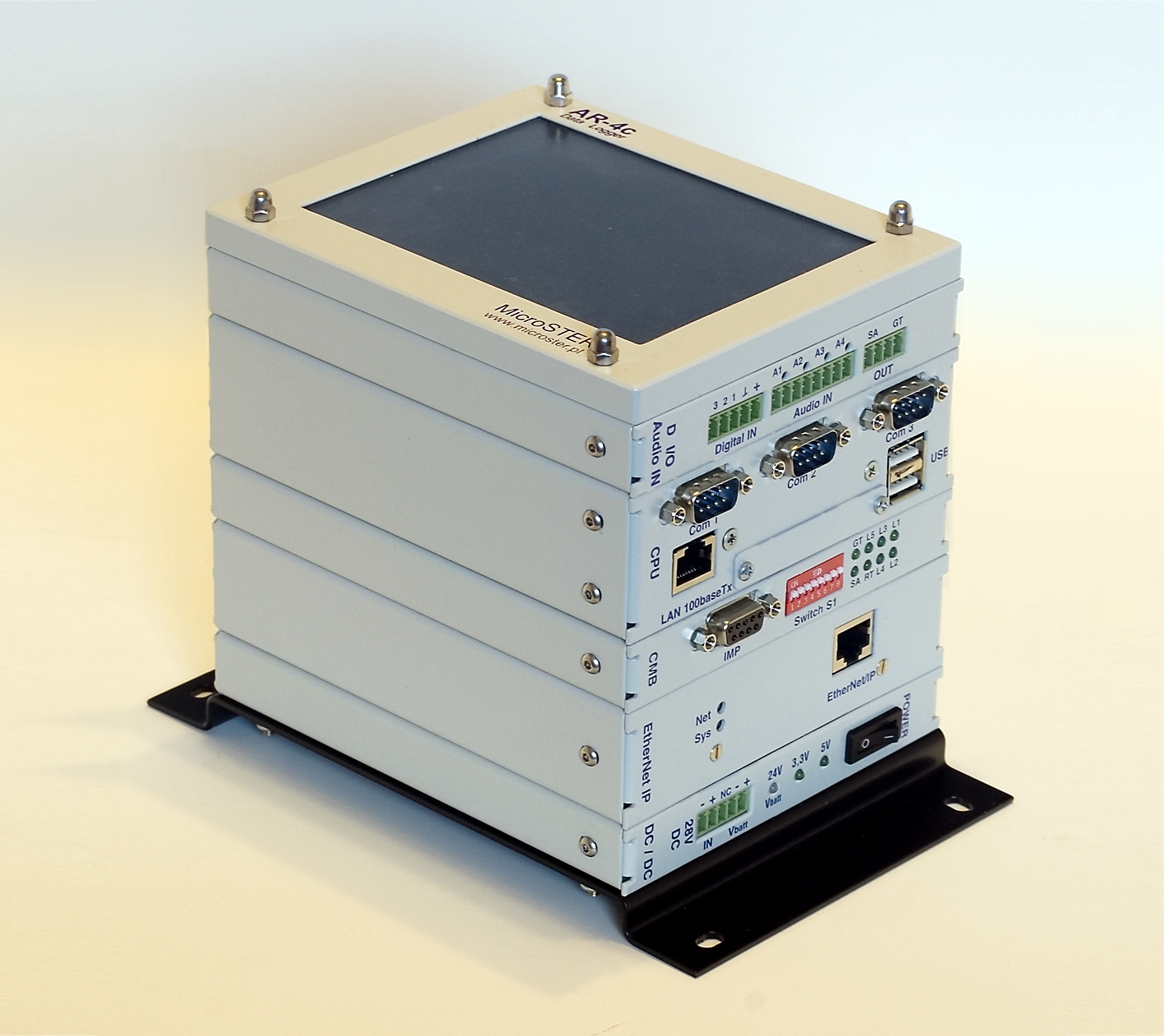
| fig.1. The AR-4c Datalogger |
The AR-4c digital datalogger is a subsequent, newest version in the AR-type dataloggers' series. It retains all functionality of its predecessor – the AR-3c datalogger, but additionally is characterized by new features and functions. The most important are:
- more compact, modular structure (based on PC/104-Plus system bus)
- inbuilt 5.7'' color LCD display (640x480 resolution) with touchscreen for visualization, control and service purposes where a special version of the ar3cmonitor program is implemented.
- inbuilt 2-channel sound recorder with internal 4 to 2 channel mixer.
- three serial RS-232 inputs for common use
- a multi functional I/O board with following inputs/outputs:
- 3 multipurpose digital inputs supplied by +24V DC power supply usually used to connect single-stroke signals
- 2 relay outputs (for READY and FAULT SIGNALING signals).
CONSTRUCTION AND WORK PRINCIPLE
|
|
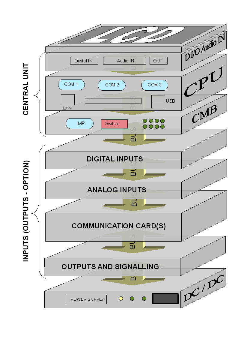
fig.2. AR-4c modular design schema
|
The AR-4c datalogger serves for logging different binary and analog signals and values characterizing the operation of various electrical circuits and devices. Although it was primarily designed for logging of the mine hoist and shaft equipment work, it can be applied in any electrical system which operational parameters should be logged. It can gather data in a classical manner through analog and binary inputs, but can also receive it from PLC controllers by means of fieldbus transmission protocols.
Additional very useful function of the AR-4c datalogger is that it can record sound information taken by four audio input channels and store it within its internal data storage. This way the necessity of use of the AR-3c – Audio sound recorder is eliminated. This feature is believed to be the main advantage of the AR-4c project since one device replaces two devices (AR-3c and AR-3c audio).
Another important feature of the AR-4c datalogger is builtin two 32-bit counters for encoders - thus it can log up to two positions and velocities without additional modules.
Thanks to its modular design and versatile software the AR-4c digital datalogger can be freely reconfigured to meet both the customer's needs and installation's demands. Thanks to advanced configuration software it can be also configured to enable basic PLC controller's functions to cooperate with other PLCs in bigger industrial control system.
A very crucial characteristic is that when equipped with several different industrial protocol communication cards it can also well serve as network integrator for fieldbus systems.
Another feature of the AR-4c Datalogger is that the logged data are stored within the so called Internal Event's Memory on a CF disk, and, for safety reasons, they can be copied to an external data storage (pen-drive). Additionally, the collected data can be printed out on a local printer, displayed on the LCD local display in a graphical manner or relayed to a visualization panel where there is a possibility to show them in the "online" mode in the form of graphical diagrams.
Next significant feature is that the AR-4c datalogger can be connected by network interface to a PC computer where the collected data can be transferred, and by specially designed program, there is the possibility to show, analyze, archive and print them in the systematic manner.
Due to embedded network interface the AR-4c datalogger can operate as a multiconnection network data server.
In order to ensure safe performance of the AR-4c datalogger its software is designed to continuously perform multiple self-tests in order to detect its internal hardware faults, and if the software functions properly (which means that the loops are realized correctly) both "Watchdog" timers are refreshed in regular time intervals, thus any software or hardware error can be immediately detected. The datalogger is equipped with two relays (output signals):
- READY relay which can serve to generating hoist's lock signal in case the AR-4c can not properly accomplish its major functions
- FAULT SIGNALING relay (is usually connected to an error lamp mounted on operator's desk) which indicate other, non critical faults.
|
|
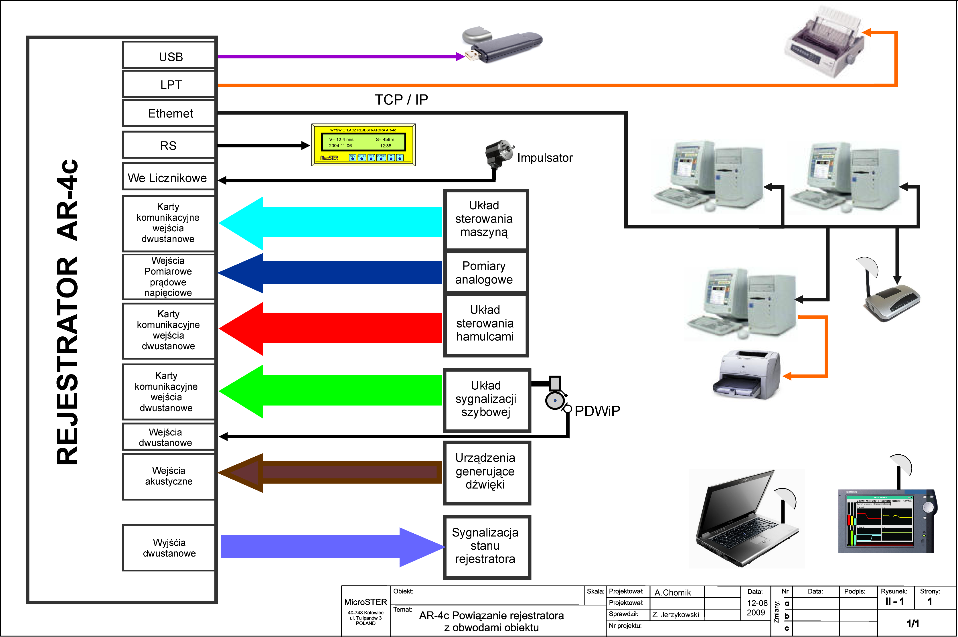
fig.3. Means of interrelating the AR-3c datalogger with hoist's systems
|
Additionally all errors are logged in a specially dedicated datalogger's memory space called Trace Memory which aim is to simplify its diagnostics and service.
Another very important feature is that the AR-4c Digital Datalogger can operate as typical "black box" storing significant data concerning the object being observed to occasionally viewing or analyzing the diagrams in case of dangerous situations or accidents, however, equipped with advanced graphical devices and communication and visualization software it can make up a significant element of modern industrial control system.
UTILITY FUNCTIONS
The AR-4c Datalogger has several significant utility functions:
- Continuous scanning of binary and analog input signals with defined frequency of range 10 Hz to 1 kHz (100 Hz by default).
- Analysis of read in data in order to detect object's state changes – each state change needs recording,
- when cooperates with an encoder for speed measurement, it may function as a digital position pointer
- recording sound information coming on audio channels
- continuously monitoring object's work on the local display
- Sending chosen data fragments from Internal Events' Memory to the CDA computer when requested by the LOGGER program operator
- Enabling network communication with all computers (client stations) through network interface,
- Enabling "online" monitoring functionality for visualization panel and local display
- Enabling visualization of object operation on the visualization panel
- Making data archives on External Data Memory linked to the USB port on request
- Web server
LCD DISPLAY
|
|
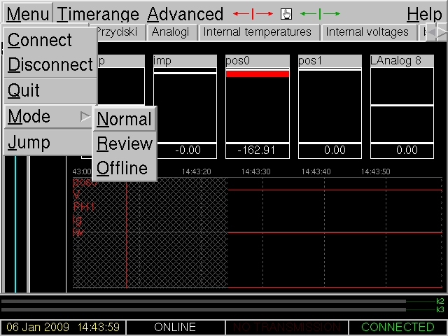
A sample screenshot of LCD display
|
The most significant advantage is incorporating of a local graphical display with a touchscreen of excellent resolution 640x480 points. Such resolution makes it possible to apply graphical user interface of a quite good quality. The 5,7'' LCD display with a touchscreen is placed on the front of the AR-4c datalogger. An excellent resolution of 640x480 pixels enables extremely powerful capabilities. On the display one can observe data in different modes:
- graphical monitoring of observed object
- analog plots in "online" and back-browsed mode
- binary plots in "online" and back-browsed mode
- fault and service logs
The display also enables some basic setting functions as time and timezone settings.
More advanced configuration capabilities can be available in protected mode.
A special version of monitoring application – Aramon was elaborated to fit within the dimensions and resolution of the display LCD screen.
The Aramon program is quite similar to its former version – AR3c-Monitor, but has several additional functions enabling simple operational tasks, among the others:
- datalogger's time and timezone settings
- pen-drive data archiving support
- local printouts support (future function)
The Aramon program if fully user-configurable and easy adjustable. Main window contains title bar (optionally), menu bar, user window and status bar. User windows are organized as tabs. Each tab has its caption. Each tab can be configured according to individual end-user request.
SOUND RECORDING METHOD
The sound which is recorded comes from four external channels which are internally multiplexed into two separate channels recorded on media. The whole of audio information input from those channels is continuously recorded within the AR-4c datalogger memory in the form of GSM format compressed one-minute files. This compression method - normally used by mobile telephony - is quite satisfactory for appropriate conversation recording so that it can be later played in an understandable way. The GSM files are stored during the period of KEEP TIME hours (this period can be set), and if they are not appointed for longer storage they are automatically erased by the system.
LOGGER PROGRAM (versions 2.0 - 4.x)
The LOGGER program is a software tool serving for communication with AR-4c, (AR-2c, AR-2c+, AR-3c) dataloggers, for visualization, archiving and graphical presentation of binary and analog signals' plots. The LOGGER program is offered in two versions:
- classical, ver. 2.0 communicates with dataloggers by means of a serial link
- network, ver. 3.1 (old) and 4.x which can communicate traditionally or through the LAN or Internet
|
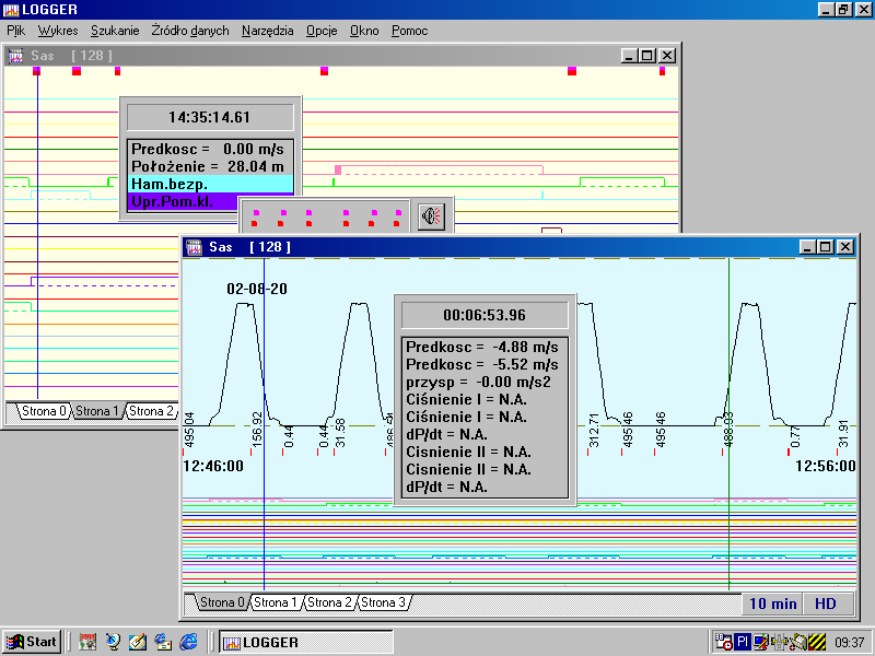
|
fig.5. A sample screenshot of LOGGER program
|
With the aid of LOGGER program it is possible to directly viewing the datalogger's Internal Events' Memory contents or transmitting the data to the hard disc or floppy disc archives. Those archive files can further be viewed on the screen or printed out on a system printer.
|
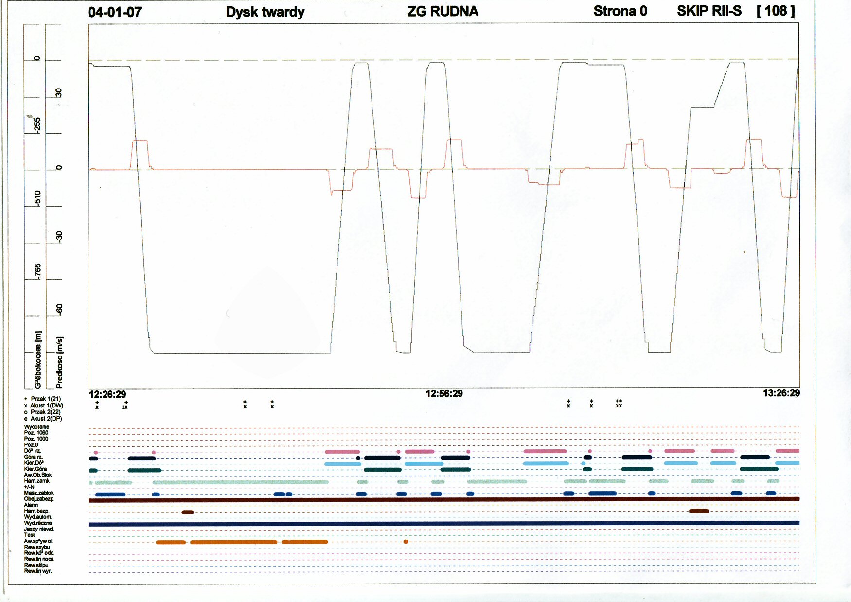
|
fig.6. A sample printout made by means of LOGGER program
|
During its work LOGGER program can create data archive files. These archives are organized in files containing data of one day length and store data transmitted from chosen datalogger. A safety method is applied in order to protect data against illegal modifications. The files are named according to the date and their extension depends on the shaft name. This information, and some other configuration parameters are duplicated, in encrypted form, within the data files themselves.
WEBSITE USEFUL FEATURES
The AR-4c datalogger's website is a very handy tool for fast and easy data transferring and a powerful aid in Logger program configuration:
- By means of "Data download" function one can transmit data from AR-4c storage (converted to Logger program format) to a computer where Logger program is installed much faster than by the Logger program itself.
- Other significant feature is the possibility to downloading and playing audio files directly from the datalogger without having to configure and use Logger program.
- The AR-4c website offers yet another interesting and helpful function: it supports binary signals configuration for Logger program.
BUILDING-UP PERIODICAL MAINTENANCE AND SERVICE
The AR-4c datalogger each time, before being installed in the object, is individually adjusted to the requirements of the installation and user's preferences. It's hardware and software configuration is set based on a project of incorporating the datalogger into the hoist's systems, created by authorized designers. It also depends on the requirements made by a user, regarding the equipment of optional external devices (printers, displays, visualization panels, external memories, utility software). An individually configured datalogger is programmed by the manufacturer, and then is subjected to a series of functional and reliability tests. Only after such a preparation is it built-up in the object and there tested once again. In the object final adjusting is done and user software is installed. All the actions should be done by the manufacturer of the datalogger or an authorized service.
In order to ensure complete continuity of the datalogger it is recommended to utilize double power for it's systems. Because of the importance of the task that the The AR-4c datalogger fulfills for the safety of a hoist it should be regularly - at least once a year - subjected to periodical maintenance and conservation. The recommended maintenance frequency is 6 months. Maintenances are carried out by the manufacturer or it's authorized representative according to the maintenance technology approved by the mining facility. During conservation a full control of recording of all signals is done, necessary adjustments and presumptively damaged elements of the datalogger are replaced. During the maintenance the necessary datalogger's upgrades and conservation of software are done. Also control and adjusting the parameters of transmission lines between the datalogger and the central data acquisition computer is done.
In case of a malfunction of the datalogger all service repairs should be done by an authorized and trained by the manufacturer service. For proper implementation of service activities it is necessary to equip the repairer with a set of original spare parts and specialized service and testing software.
PARAMETERS
| PARAMETER DESCRIPTION | PARAMETER VALUE | |
| 1 | 2 | |
| Input voltage | 20V - 30V DC or 90 - 260V AC (with external power supply) | |
| Input voltage latitude | as above | |
| Power consumption | up to 30VA, standard 15VA | |
| environment operating temperature | 5 - 50oC | |
| environment storage temperature | -40oC - +90oC | |
| operating air relative humidity (by 30 |
30% - 85% | |
| storage air relative humidity (by 30 |
up to 95% | |
| dimensions (default configuration i.e. without binary and analog inputs | 155 × 125 × 160 mm | |
| dimensions with base | 200 × 125 × 160 mm | |
| weight | 3 kg | |
| backup power supply (battery) operating time | above 2 hours (depending on batteries - with new 2,9Ah batteries the time extends to 4 -5 hours) | |
| binary inputs | number of binary signals logged | up to 4080 |
| input voltage for binary inputs | 24V, 48V, 220V, 110V DC | |
| binary inputs input voltage latitude | +-35% | |
| input signals current | 4.5 - 10mA | |
| sampling interval | 2 -10ms (parameter depends on configuration) | |
| input signals galvanic insulation | 1000 - 2500 V | |
| analog inputs (A/C converter data) | number of analog signal inputs | up to 32 |
| analog signals input voltage | -10V - +10V, -20V - +20V, -100V - +100V | |
| logger current range | -20ma - +20mA | |
| measured voltage types | DC and AC | |
| sampling interval | 1.5 - 30ms (programmable) | |
| sampling interval | 1.5 - 30ms (programmable) | |
| measurement logging precision | 0,05% (precision for cards 8(16) analog inputs with 12 bits converter | |
| measurement channels galvanic insulation | 1000 - 2500 V | |
| Analog signals (i.e. from PLCs) | quantity | up to 255 (16 bit words) |
| sampling interval | 2 - 10ms (parameter depends on configuration) | |
| resolution | 16 or 32 bits | |
| multipurpose inputs i.e. for acoustic converter | number of signals | 3 (4) 24V DC |
| logging resolution | 20ms (programmable) | |
| Audio inputs | number of channels | 4 |
| input voltage | max +/- 2,5V | |
| Quadrature counter | number | 1 - 2 |
| outputs | number of relay outputs | 2 |
| output voltage and current | 24V, 0,5A | |
| Datalogger's case dust proof | at least IP-40 | |
| measured voltages type | AC & DC | |
