
The AR-3c Datalogger
GENERAL CHARACTERISTICS
|
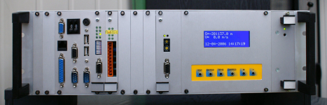
| fig.1. The AR-3c Digital Datalogger |
The AR-3c Datalogger is made for recording the progress of physical quantities that characterize the work of different machines and devices. These quantities, acquired by various sensors and transducers, are represented, depending on their character, in the form of electrical, analog or binary values. In it's primary form it has been designed for recording the selected parameters and conditions of mine hoist enabling recording all, required by the regulations, signals and quantities from the shaft signaling and hoist control system. The AR-3c Digital Datalogger ensures complete implementation of the requirements contained in polish mining law and has the admission of the Higher Mining Office for utilization in underground mining facilities as a separate hoist's assembly (admission characteristic GE 18-05).
CONSTRUCTION AND WORK PRINCIPLE
|
|
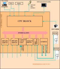
fig.2. Block diagram of AR-3c datalogger
|
A block diagram of the AR-3c Digital Datalogger has been presented in Figure 2.. Recorded signals are routed to the input systems through intermediary circuits containing the required sensors and transducers, some of which are an integral part of the datalogger itself. The input systems, due to their modular construction, are easy to reconfigure and expand. One can connect up to 4096 binary signals and 32 analog signals to the datalogger. All the inputs possess galvanic separation in range of 1kV to 2.5kV. The datalogger also has two specialized inputs for recording single stroke signals and 2 fast counter inputs used for connecting incremental encoders in order to record the position. Thanks to this it is possible to record the precise speed of the hoist and the conveyance's position within the shaft.
There are also modules attached that enable cooperation with PLC controllers, enabling fieldbus communication in PROFIBUS DP, MODBUS RTU, CANBUS and other standards. This makes it possible to easy system integration in various industrial fieldbus standards. Due to equipping the AR-3c datalogger with input systems it is possible to record many diverse critical parameters, such as the currents in motors' circuits, pressures of the medium in brakes' or temperature.
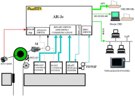
In order to expand the functionality and easiness of configuration, the operation of AR-3c datalogger is based on a multi-tasking real-time operating system, which ensures reliable and efficient work of the datalogger and enriches it's utility values. figure 3 shows typical methods of connecting AR-3c datalogger to hoist's systems.
The datalogger by default scans the binary and analog inputs with the frequency of 100 Hz, but it is possible to increase this frequency to 1000 Hz.
Additionally, due to equipping the datalogger with a display, and when it cooperates with an encoder for speed measurement, it may function as a digital position indicator. The display of the datalogger also is used for displaying the hoist's velocity and other analog quantities and the range of acquired data.
A very crucial characteristic of the AR-3c Digital Datalogger is recording of single stroke signals with the use of acoustic PDWiP sensors, which ensures, that the device records information about bell's clangs, that have actually reached the operator's ears. The AR-3c datalogger, due to it's construction, can record data from 2 mine hoists simultaneously.
|
|
fig.3. Means of interrelating the AR-3c datalogger with hoist's systems
|
Recorded data is compressed and placed in the up to 1GB Internal Events Memory. The Internal Events Memory may be doubled to ensure the safety of recording. The data recorded in the memory can be transferred to the central data acquisition computer in order to store, report or visualize, print in the form of graphs on a local printer connected to the datalogger or copy onto an external mass storage device (electronic "pen-drive"-type disc). For the reasons of communication with the central data acquisition station the AR-3c datalogger is equipped with a network interface and a double channel serial transmission port, and two USB ports used for storing data and visualization.
The AR-3c Digital Datalogger can be fully resistant to power-down conditions, and, due to utilization of two independent Watch-Dog-type timers, it enables full self-control and sends a signal enabling hoist's lock in case of a malfunction. The cassette with datalogger's modules along with the terminal streeps, transmission converters or network switches and a printer may be enclosed in a dustproof housing, ensuring a class IP-54 tightness.
INTERNAL EVENTS MEMORY
The construction of this memory protects the data stored in it from being lost, and the procedures of accessing it protect against incidental erasure. The capacity - 100 MB to 1 GB - enables saving all signals collected by the datalogger in the period of at least 14 days of hoist's operation. (Default is 2 months). The internal events memory is organized in 1 - minute blocks, which are indivisible.
OPERATING PANEL (VISUALIZATION PANEL)
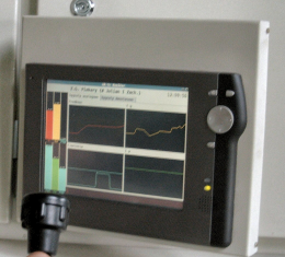
The visualization panel is an independent, optionally attached module equipped with a LCD touchscreen. By default a SL4-type panel is used with the diagonal of 8.4", the resolution of 800 x 600 at 16 bit color. In Figure 4 a visualization panel is shown with a working visualization program AR3CMONITOR. The visualization panel cooperates with the AR-3c datalogger through a network port or a USB port.
| |
|
fig.4. The AR-3c visualization panel
|
Panel's software (the visualization program AR-3C MONITOR) enables reading analog and binary data from the datalogger and current displaying of this data both in the form of graphs and text information. A version of the AR-3C MONITOR program which enables internal events memory back browsing in the selected by user resolution is also offered. It is also possible to run AR3C MONITOR on an ordinary PC.
The main visualization window is used for selecting the visualization screen. On the following screens information coming from different hoist's systems are available. On the AR3C-MONITOR program screens are available:
- analog signals bar plots
- binary and analog signals timing diagrams
- single stroke signals' series timing diagrams
- binary signals screens organized in form of sets of flashing lamps and text information
- a screen with diagnostic information.
Selecting the screen and the tab within the screen is made by touching with a finger or with the attached touch-pen the appropriate place (key, tab description) on the touch-screen.
LOCAL PRINTER
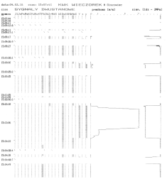
The AR-3c Digital Datalogger may be equipped with a local printer used for creating current charts of hoist's work. A sample chart is shown in Figure 5. In order to create local print-outs by default an OKI 280 Microline printer is used, which is characterized by good durability and reliability parameters.
|
|
fig.5. A sample local print-out
|
CENTRAL DATA RECORDING STATION
|
|
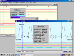
fig.6. A sample screenshot of LOGGER program
|
Central Data Acquisition station is a PC-class computer, to which usually all or some AR-3c dataloggers are connected (or/and it's predecessors - AR-2c) installed in the given mining facility. A special program called the LOGGER is installed on this computer, dedicated to operating AR-type dataloggers. LOGGER in versions 3.1 - 4.3 and further is a networking program used for visualizing and storing analog and binary diagrams and single stroke signals' series read from the winding gear circuits. A sample screenshot of the LOGGER program is shown on figure 6. The program cooperates with AR-3c dataloggers in a computer network (including wireless networks) or through a RS-232 serial port. Thanks to equipping the AR-3c datalogger with a network interface it is possible to communicate simultaneously with the datalogger from many central data acquisition stations, it is possible to directly browse through the contents of the dataloggers's memory, and also saving data from the datalogger to computer's hard disc or floppy. The stored data are available for viewing at any time.
In a case, when the AR-3c datalogger is installed in a place devoid of the possibility of connecting it to a network, it is possible to save the recorded data onto a portable electronic disc ("pen-drive"-type). This data are saved in the LOGGER file format and may be later transferred to the computer. This feature is a convenient alternative for transmitting the data through a classic serial line.
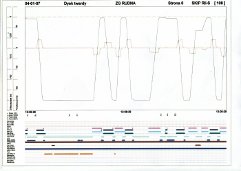
The LOGGER program is equipped with a user-friendly graphical interface allowing to easily draw charts from the datalogger on the screen and their analysis. The data graphs can also be printed on the printer connected to the computer. A sample printout is shown in Figure 7.
|
|
fig.7. A sample printout made by means of LOGGER program
|
The program can also cooperate with several AR-2c and AR-3c Digital Datalogger in the field of storing data and visualization. Due to equipping the LOGGER program with the feature of reporting it is possible to create and compile reports, which type and amount may be declared by the user according to his current needs and requirements. It is also possible to switch LOGGER into the "On line" mode for current tracking of the mine hoist's operation.
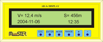
POSITION INDICATOR
|
|
fig.8. Depth indicator
|
In the dataloggers, that have been equipped with an encoder during the machine's motion on the display, aside from it's velocity, information about conveyance's position in the shaft is also shown. In order for this information to be reliable it is necessary to connect to the datalogger's signals from the location signal transmitters (i.e. magnetic switches) installed in the shaft, which are used for correcting any indications of depth indicators. The position indication can also be recorded in the dataloggers's memory and displayed in the form of a chart or numerical indications on a local printout and in the Central Data Acquisition computer.
THE AR-3C IN NETWORK
|
|
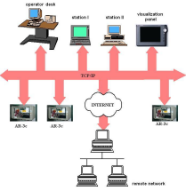
fig.9. A sample networking configuration of AR-3c datalogger
|
A network version of LOGGER software (v3.0 and later) enables acquiring and analysis of the data in AR-3c dataloggers using computers working in a Ethernet-type network. On Figure 8 some ideas of AR-3c and LOGGER program networking possibilities and configuration are shown. An advantage of this software is the possibility of multi-station working. Unlike it's predecessor - the AR-2c datalogger, AR-3c datalogger is a multi-connection network server, which makes it possible to simultaneously access data in it's memory by many clients of the central data acquisition station.
BUILDING-UP PERIODICAL MAINTENANCE AND SERVICE
The AR-3c Digital Datalogger each time, before being installed in the object, is individually adjusted to the requirements of the installation and user's preferences. It's hardware and software configuration is set based on a project of incorporating the datalogger into the hoist's systems, created by authorized designers. It also depends on the requirements made by a user, regarding the equipment of optional external devices (printers, displays, visualization panels, external memories, utility software). An individually configured datalogger is programmed by the manufacturer, and then is subjected to a series of functional and reliability tests. Only after such a preparation is it built-up in the object and there tested once again. In the object final adjusting is done and user software is installed (LOGGER, AR3C-MONITOR). All the actions should be done by the manufacturer of the datalogger or an authorized service.
In order to ensure complete continuity of the datalogger it is recommended to utilize double power for it's systems. Because of the importance of the task that the The AR-3c Digital Datalogger fulfills for the safety of a hoist it should be regularly - at least once a year - subjected to periodical maintenance and conservation. The recommended maintenance frequency is 6 months. Maintenances are carried out by the manufacturer or it's authorized representative according to the maintenance technology approved by the mining facility. During conservation a full control of recording of all signals is done, necessary adjustments and presumptively damaged elements of the datalogger are replaced. During the maintenance necessary upgrades are done and conservation of software of the datalogger. Also control and adjusting the parameters of transmission lines between the datalogger and the central data acquisition computer is done.
In case of a malfunction of the datalogger all service repairs should be done by an authorized and trained by the manufacturer service. For proper implementation of service activities it is necessary to equip the repairer with a set of original spare parts and specialized service and testing software.
PARAMETERS
| PARAMETER DESCRIPTION | PARAMETER VALUE | |
| 1 | 2 | |
| Power supply | 18V - 30V DC or 100-280V AC | |
| Power supply tolerance | as above | |
| Power consumption | no more than 50VA | |
| Ambient temperature during work | 5 - 40oC | |
| Ambient temperature during transportation and storage | -40oC - +70oC | |
| Relative humidity at 30oC during work during transportation |
30...85% do 95% |
|
| Dimensions | 480 × 254 × 134 mm | |
| Weight | 7 kg | |
| Logging time after power down | no less than 1 hour | |
| Binary inputs | quantity | 20 - 4096 |
| input voltages | 24 V, 48 V, 220 V, 110 V DC | |
| input voltages tolerance | ±35% | |
| input currents | 4,5 - 10 mA | |
| scanning resolution (frequency) | 100 us - 10 ms | |
| isolation | 1000 - 2500 V | |
| Analog inputs | quantity | up to 32 |
| input voltages | -10... +10 V -20... +20 V -100 ... +100 V |
|
| input currents | -20 ... +20 mA | |
| measured voltages type | AC & DC | |
| scanning frequency | 100 us - 100 ms | |
| measurement accuracy | 12 bits + sign bit (max 18 bits)** | |
| logging accuracy | 0,05% | |
| isolation of measurement channels | 1000 - 2500 V | |
| Acoustic inputs | quantity | 2 (4) |
| logging resolution | 20 ms | |
| Counter inputs | quantity | 1 |
| Outputs | quantity of relay outputs | 1 lub 2 |
| Case dust proof AR-3c | no worse than IP-54 | |
